Страница 1 из 2
Поделиться этой страницей

This product is component of system.
For details, refer to “Important symbols for good services”.
4-1, Meguro 1-chome, Meguro-ku, Tokyo 153-8654, Japan PIONEER ELECTRONICS (USA) INC. P.O. Box 1760, Long Beach, CA 90801-1760, U.S.A. PIONEER EUROPE NV Haven 1087, Keetberglaan 1, 9120 Melsele, Belgium
PIONEER ELECTRONICS ASIACENTRE PTE. LTD. 253 Alexandra Road, #04-01, Singapore 159936 PIONEER CORPORATION 2002
T – IZE JAN. 2002 Printed in Japan
This service manual is intended for qualified service technicians ; it is not meant for the casual do-it- yourselfer. Qualified technicians have the necessary test equipment and tools, and have been trained to properly and safely repair complex products such as those covered by this manual.
Improperly performed repairs can adversely affect the safety and reliability of the product and may void the warranty. If you are not qualified to perform the repair of this product properly and safely, you should not risk trying to do so and refer the repair to a qualified service technician.
This product contains lead in solder and certain electrical parts contain chemicals which are known to the state of California to cause cancer, birth defects or other reproductive harm.
Health & Safety Code Section 25249.6 – Proposition 65
(FOR CANADIAN MODEL ONLY)
(fast operating fuse) and/or
(slow operating fuse) on PCB indicate that replacement parts must be of identical designation.
(POUR MODÈLE CANADIEN SEULEMENT)
Les symboles de fusible
(fusible de type rapide) et/ou
(fusible de type lent) sur CCI indiquent que les pièces de remplacement doivent avoir la même désignation.
Comply with all cautions and safety related notes located on or inside the cabinet and on the chassis.
When service is required, even though the PDP UNIT an isolation transformer should be inserted between the power line and the set in safety before any service is performed.
When replacing a chassis in the set, all the protective devices must be put back in place, such as barriers, nonmetallic knobs, adjustment and compartment covershields, isolation resistorcapacitor, etc.
When service is required, observe the original lead dress. Extra precaution should be taken to assure correct lead dress in the high voltage circuitry area.
Always use the manufacture’s replacement components. Especially critical components as indicated on the circuit diagram should not be replaced by other manufacture’s.
Furthermore where a short circuit has occurred, replace those components that indicate evidence of overheating.
Always return the internal wiring to the original styling.
Attach parts (Gascket, Ferrite Core, Ground, Rear Cover, Shield Case etc.) surely after disassembly.
When the front case is removed, make sure nothing hits the panel face, panel corner, and panel edge (so that the glass does not break).
Make sure that the panel vent does not break. (Check that the cover is attached.)
Handle the FPC connected to the panel carefully.
Twisting or pulling the FPC when connecting it to the connector will cause it to peel off from the panel.
When the front case is removed, infrared ray is radiated and may disturb reception of the remote control unit.
Pay extreme caution when the front case and rear panel are removed because this may cause a high risk of disturbance to TVs and radios in the surrounding.
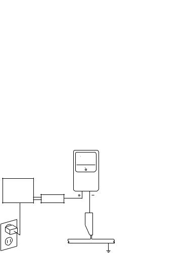
Leakage Current Cold Check
With the AC plug removed from an AC power source, place a jumper across the two plug prongs. Turn the AC power switch on. Using an insulation tester (DC 500V), connect one lead to the jumpered AC plug and touch the other lead to each exposed metal part (input/output terminals, screwheads, metal overlays, control shafts, etc.), particularly any exposed metal part having a return path to the chassis. Exposed metal parts having a return path to the chassis should have a minimum resistor reading of 0.3Mand a maximum resistor reading of 5M. Any resistor value below or above this range indicates an abnormality which requires corrective action. Exposed metal parts not having a return path to the chassis
will indicate an open circuit.
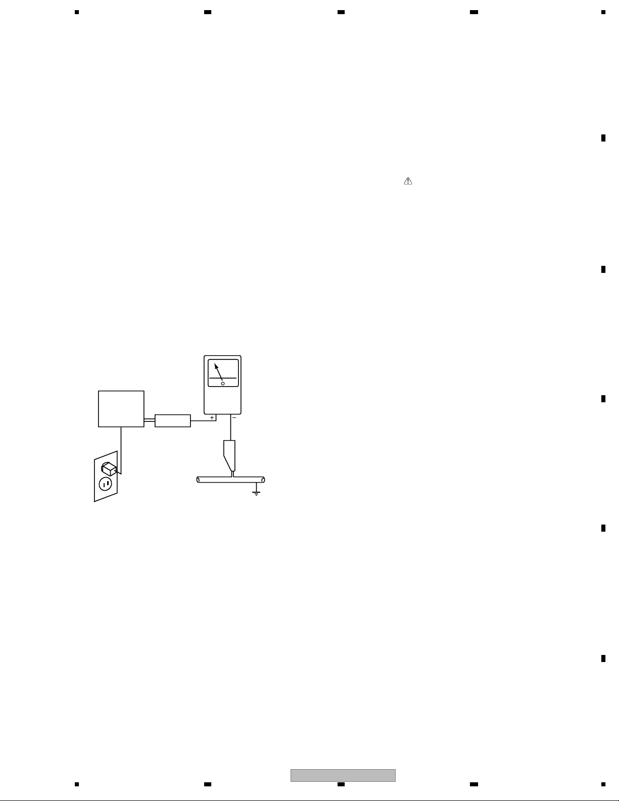
Leakage Current Hot Check
Plug the AC line cord directly into an AC power source (do not use an isolation transformer for this check).
Using a “Leakage Current Tester (Simpson Model 229 equivalent)”, measure for current from all exposed metal parts of the cabinet (input/output terminals, screwheads, metal overlays, control shaft, etc.), particularly any exposed metal part having a return path to the chassis, to a known earth ground (water pipe, conduit, etc.). Any current measured must not exceed 0.5mA.
Also test with plug reversed
(Using AC adapter plug as required)
AC Leakage Test
ANY MEASUREMENTS NOT WITHIN THE LIMITS OUTLINED ABOVE ARE INDICATIVE OF A POTENTIAL SHOCK HAZARD AND MUST BE CORRECTED BEFORE RETURNING THE SET TO THE CUSTOMER.
PRODUCT SAFETY NOTICE
Many electrical and mechanical parts in PIONEER set have special safety related characteristics. These are often not evident from visual inspection nor the protection afforded by them necessarily can be obtained by using replacement components rated for higher voltage, wattage, etc. Replacement parts which have these special safety characteristics are identified in this Service Manual.
Electrical components having such features are identified by marking with a
on the schematics and on the parts list in this Service Manual.
The use of a substitute replacement component which dose not have the same safety characteristics as the PIONEER recommended replacement one, shown in the parts list in this Service Manual, may create shock, fire or other hazards.
Product Safety is continuously under review and new instructions are issued from time to time. For the latest information, always consult the current PIONEER Service Manual. A subscription to, or additional copies of, PIONEER Service Manual may be obtained at a nominal charge from PIONEER.
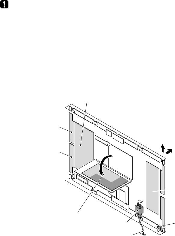
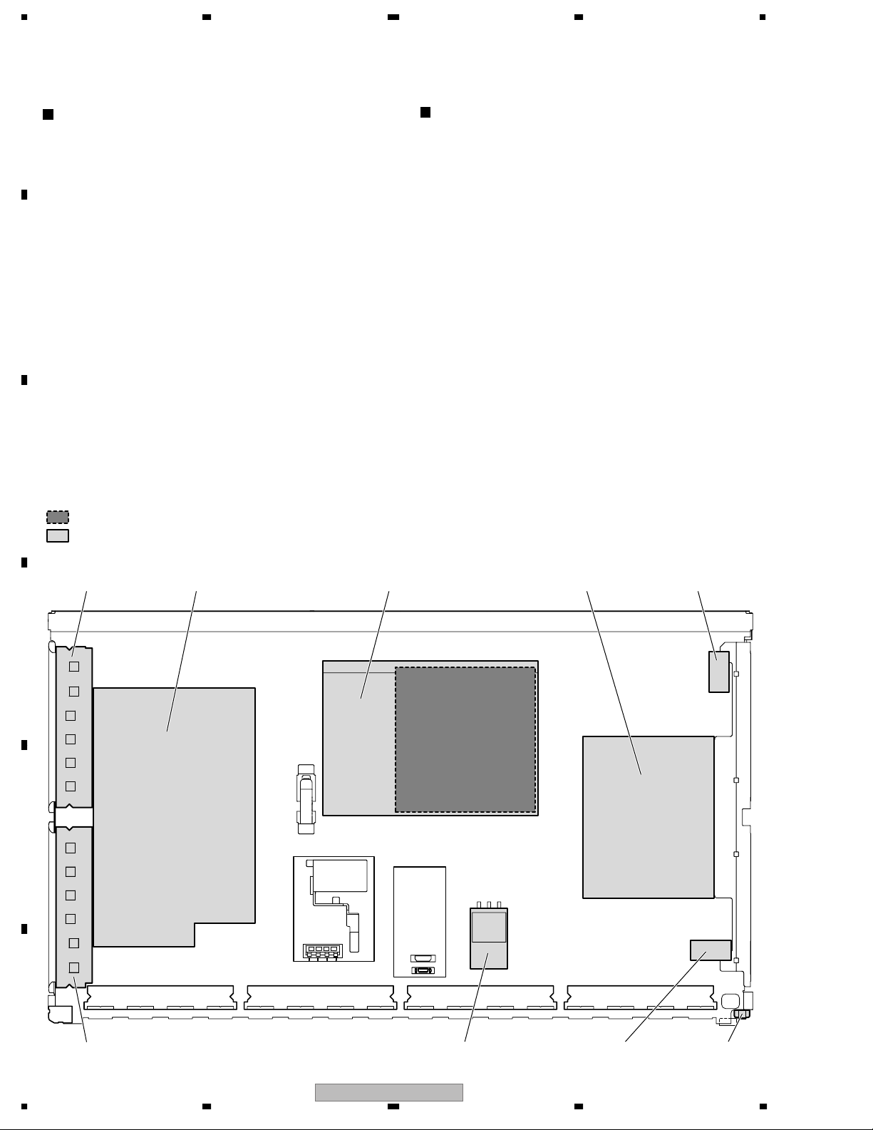
CHARGED SECTION AND HIGH VOLTAGE GENERATING POINT
The places where the commercial AC power is used without passing through the power supply transformer.
If the places are touched, there is a risk of electric shock. In addition, the measuring equipment can be damaged if it is connected to the GND of the charged section and the GND of the non-charged section while connecting the set directly to the commercial AC power supply. Therefore, be sure to connect the set via an insulated transformer and supply the current.
AC Power Cord
AC Inlet with Filter
Power Switch (S1)
Fuse (In the SW POWER SUPPLY Module)
STB Transformer and Converter Transformer (In the SW POWER SUPPLY Module)
Other primary side of the SW POWER SUPPLY Module
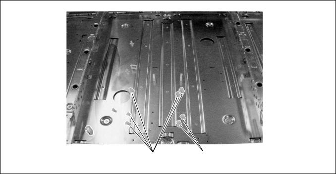
Remove the IF Earth Metal (No.3 on the page 25) beforehand when inclines the power supply unit as the right figure.
The places where voltage is 100V or more except for the charged places described above. If the places are touched, there is a risk of electric shock.
: Part is the High Voltage Generating Points other than the Charged Section.
X CONNECTOR (A)
X CONNECTOR (B)
Fig.1 Charged Section and High Voltage Generating Point (Rear View)
In this manual, the symbols shown-below indicate that adjustments, settings or cleaning should be made securely. When you find the procedures bearing any of the symbols, be sure to fulfill them:
1. Product safety
To keep the original performances of the product, optimum adjustments or specification confirmation is indispensable. In accordance with the procedures or instructions described in this manual, adjustments should be performed.
For optical pickups, tape-deck heads, lenses and mirrors used in projection monitors, and other parts requiring cleaning, proper cleaning should be performed to restore their performances.
4. Shipping mode and shipping screws
To protect the product from damages or failures that may be caused during transit, the shipping mode should be set or the shipping screws should be installed before shipping out in accordance with this manual, if necessary.
5. Lubricants, glues, and replacement parts
Appropriately applying grease or glue can maintain the product performances. But improper lubrication or applying
• Design and specifications are subject to change without notice.
Binder Assy (AEC1908)
2. EXPLODED VIEWS AND PARTS LIST
Screws adjacent to
mark on the product are used for disassembly.
PACKING PARTS LISTParts marked by “NSP” are generally unavailable because they are not in our Master Spare Parts List.NOTES:
(2) CONTRAST TABLE
2.2 UNDER LAYER SECTION (1)
“2.14 PANEL CHASSIS (43) ASSY 9 (AWU1038)”.
UNDER LAYER SECTION (1) PARTS LIST
2.3 UNDER LAYER SECTION (2)
UNDER LAYER SECTION (2) PARTS LIST
2.4 UNDER LAYER SECTION (3)
2.5 UNDER LAYER SECTION (4)
UNDER LAYER SECTION (4) PARTS LIST

2.6 UNDER LAYER SECTION (5)
1 or 2
UNDER LAYER SECTION (5) PARTS LIST
2.7 UNDER LAYER SECTION (6)
UNDER LAYER SECTION (6) PARTS LIST
2.8 MIDDLE LAYER SECTION (1)
MIDDLE LAYER SECTION (1) PARTS LIST
2.9 MIDDLE LAYER SECTION (2)
MIDDLE LAYER SECTION (2) PARTS LIST
2.10 UPPER LAYER SECTION (1)
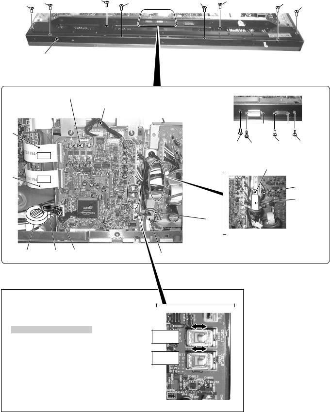
Caution in the MR INTERFACE Assy
Set the slide switches in accordance with applicabe model when replacing the MR INTERFACE Assy.
Note 1: When there is not S4004, set only S4001. Note 2: When there are not S4001 and S4004,
setting is unnecessary.
UPPER LAYER SECTION (1) PARTS LIST
2.11 UPPER LAYER SECTION (2)
(1) UPPER LAYER SECTION (2) PARTS LIST

2.13 REAR SECTION
2.14 PDP SERVICE ASSY 433 (AWU1043)
2.15 PANEL CHASSIS (43) ASSY (AWU1038)
Confirm character carved a seal near the parts, and remove it.
P : Public exclusive use
W : Module exclusive use
PW : Common use of public use and module
In case of this unit, the parts that “W” is marked removes.
Circuit Board Spacer Circuit Board Spacer (AEC1872) (AEC1872)
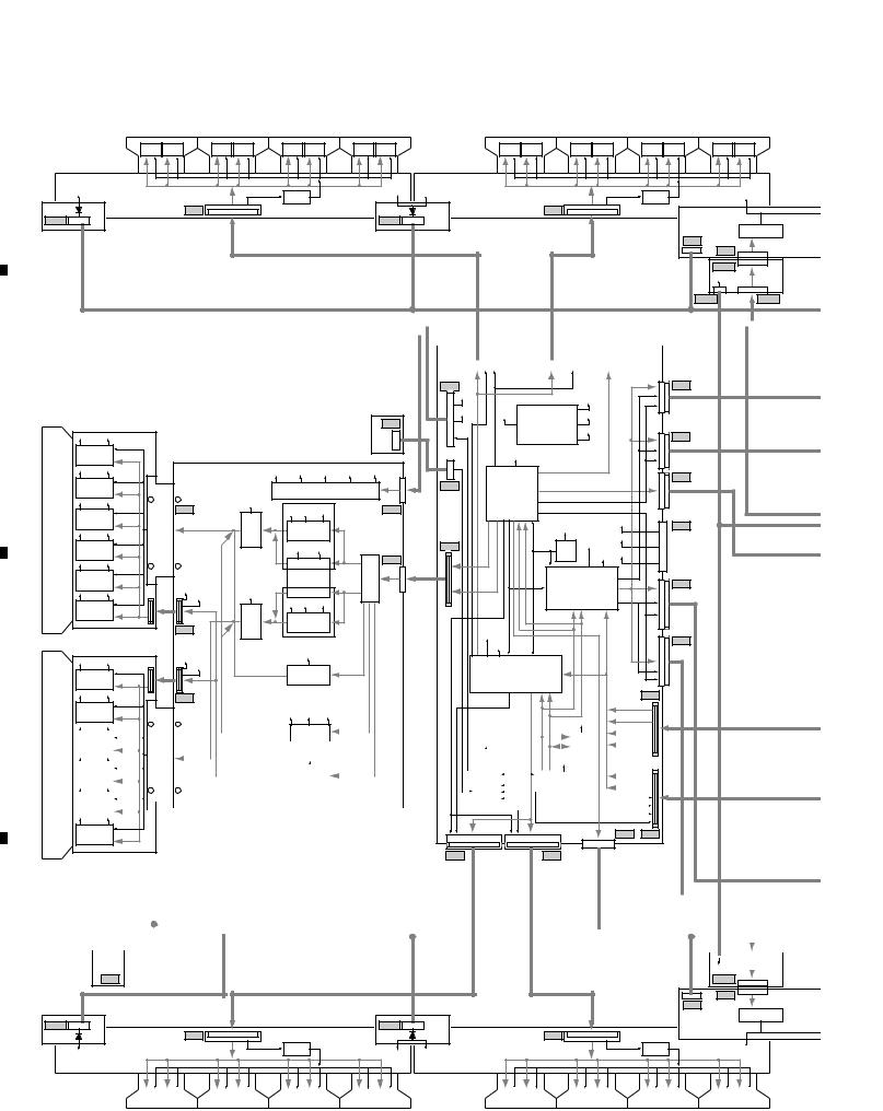
3.1.1 OVERALL DIAGRAM
Note : When ordering service parts, be sure to refer to “EXPLODED VIEWS and PARTS LIST” or “PCB PARTS LIST”.
System Cable Connector
AUDIO AMP ASSY
SRS & Focus
X CONNECTOR (A) ASSY
X CONNECTOR (B) ASSY

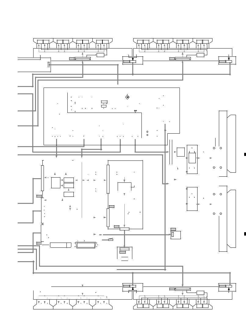
3.1.2 MR INTERFACE ASSY

CN4002 (MDR Connector) (Media Receiver)
CN4003 (DVI Connector) (Media Receiver)
CN4004 (50P_FFC Connector) (DIGITAL VIDEO Assy)
CN4005 (50P_FFC Connector) (DIGITAL VIDEO Assy)
PIONEER CORPORATION 4-1, Meguro 1-chome, Meguro-ku, Tokyo 153-8654, Japan
PIONEER ELECTRONICS (USA) INC. P.O. Box 1760, Long Beach, CA 90801-1760, U.S.A.
PIONEER EUROPE NV Haven 1087, Keetberglaan 1, 9120 Melsele, Belgium
PIONEER ELECTRONICS ASIACENTRE PTE. LTD. 253 Alexandra Road, #04-01, Singapore 159936
PIONEER CORPORATION 2005
Model Type Power Requirement Remarks
PDP-436PE WYVI AC220 – 240V
PDP-436PU KUCXC AC120V
Model No. Order No. Remarks
PDP-436PE, PDP-436PU ARP3272 SCHEMATIC DIAGRAM, PCB CONNECTION DIAGRAM
Media Receivers up to Generation 5 (G5) cannot be connected with this unit.
Be sure to use a Media Receiver of Generation 6 (G6) (ex.: PDP-R06, etc.).
For details, refer to “Important Check Points for good servicing”.
T-IZR SEPT. 2005 printed in Japan

SAFETY INFORMATION
do-it-yourselfer. Qualified technicians have the necessary test equipment and tools, and have been
Health & Safety Code Section 25249.6 – Proposition 65
Fuse symbols (fast operating fuse) and/or (slow operating fuse) on PCB indicate that replacement parts
Les symboles de fusible (fusible de type rapide) et/ou (fusible de type lent) sur CCI indiquent que les pièces
NOTICE : Comply with all cautions and safety related notes
1. When service is required, even though the PDP UNIT an
2. When replacing a chassis in the set, all the protective devices
adjustment and compartment covershields, isolation resistor-
3. When service is required, observe the original lead dress. Extra
precaution should be taken to assure correct lead dress in the
4. Always use the manufacture’s replacement components.
5. Before returning a serviced set to the customer, the service
technician must thoroughly test the unit to be certain that it is
completely safe to operate without danger of electrical shock,
and be sure that no protective device built into the set by the
manufacture has become defective, or inadvertently defeated
performed for the continued protection of the customer and
and rise in internal temperature.
• Always return the internal wiring to the original styling.
• Attach parts (Gascket, Ferrite Core, Ground, Rear Cover,
• When the front case is removed, make sure nothing hits the
• Make sure that the panel vent does not break. (Check that the
• Handle the FPC connected to the panel carefully.
• Pay extreme caution when the front case and rear panel are
the chassis will indicate an open circuit.
conduit, etc.). Any current measured must not exceed 0.5mA.
marking with a on the schematics and on the parts list in this
not be above
43 SCAN B Assy
43 SCAN A Assy SUS CLAMP 2 Assy Power Switch (S1)
1. Power Cord
2. AC Inlet
3. Power Switch (S1)
4. Fuse (In the POWER SUPPLY Unit)
5. STB Transformer and Converter Transformer
6. Other primary side of the POWER SUPPLY Unit
If the procedures described in “7.1.5 POWER ON/OFF
FUNCTION FOR THE LARGE-SIGNAL SYSTEM” are
performed before the power is turned off, the voltage will be
discharged in about 30 seconds.
: Part is Charged Section.
43 Y DRIVE Assy 43 X DRIVE Assy SUS CLAMP 1 Assy

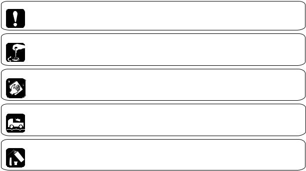
In this manual, procedures that must be performed during repairs are marked with the below symbol.
Please conform to product regulations (such as safety and radiation regulations), and maintain a safe servicing environment by
1 Use specified parts for repair.
Use genuine parts. Be sure to use important parts for safety.
2 Do not perform modifications without proper instructions.
radio/TV interference and foreign noise.
3 Make sure the soldering of repaired locations is properly performed.
When you solder while repairing, please be sure that there are no cold solder and other debris.
Soldering should be finished with the proper quantity. (Refer to the example)
4 Make sure the screws are tightly fastened.
Please be sure that all screws are fastened, and that there are no loose screws.
5 Make sure each connectors are correctly inserted.
Please be sure that all connectors are inserted, and that there are no imperfect insertion.
6 Make sure the wiring cables are set to their original state.
Please replace the wiring and cables to the original state after repairs.
In addition, be sure that there are no pinched wires, etc.
7 Make sure screws and soldering scraps do not remain inside the product.
Please check that neither solder debris nor screws remain inside the product.
8 There should be no semi-broken wires, scratches, melting, etc. on the coating of the power cord.
Damaged power cords may lead to fire accidents, so please be sure that there are no damages.
If you find a damaged power cord, please exchange it with a suitable one.
9 There should be no spark traces or similar marks on the power plug.
When spark traces or similar marks are found on the power supply plug, please check the connection and advise on secure
connections and suitable usage. Please exchange the power cord if necessary.
0 Safe environment should be secured during servicing.
When you perform repairs, please pay attention to static electricity, furniture, household articles, etc. in order to prevent injuries.
Please pay attention to your surroundings and repair safely.
To keep the original performance of the products, optimum adjustments and confirmation of characteristics within specification.
Adjustments should be performed in accordance with the procedures/instructions described in this manual.
For parts that require cleaning, such as optical pickups, tape deck heads, lenses and mirrors used in projection monitors, proper
3. Lubricants, Glues, and Replacement parts
Use grease and adhesives that are equal to the specified substance.
Make sure the proper amount is applied.
5. Shipping mode and Shipping screws
To protect products from damages or failures during transit, the shipping mode should be set or the shipping screws should be

CONTENTS
SPECIFICATIONS
Item 43″ Plasma Display, Model: PDP-436PE 43″ Plasma Display, Model: PDP-436PU
Number of Pixels 1024
13 W + 13 W (1 kHz, 10 %, 8)
220 – 240 V AC, 50/60 Hz, 344 W (0.4 W Standby)
1076 (W) 632 (H) 92 (D) mm
25.8 kg (56.9 lbs.)
120 V AC, 60 Hz, 296 W (0.2 W Standby)
(42 3/8 (W) 24 29/32 (H) 3 5/8 (D) inches)
• FOCUS, WOW, SRS and symbol are trademarks of SRS Labs, Inc.
FOCUS and SRS technologies are incorporated under license from SRS Labs, Inc.
• This product includes FontAvenue fonts licensed by NEC Corporation.
FontAvenue is a registered trademark of NEC Corporation.
• HDMI, the HDMI logo and High-Definition Multimedia Interface are trademarks or registered trademarks of HDMI Licensing
• The names of companies or institutions are trademarks or registered trademarks of the respective companies or institutions.
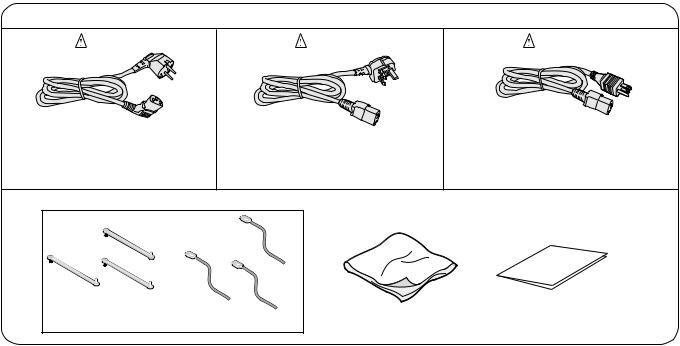
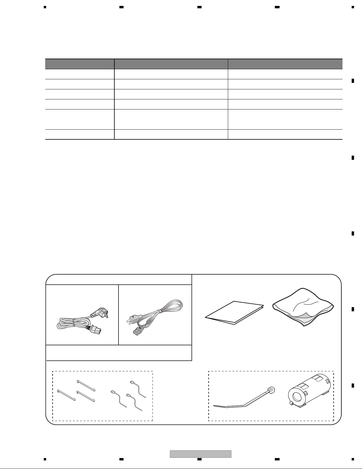
Power cord (2 m)
Only the power cord that is appropriate in your country or region
Speed clamp x 3 Bead band x 3
Binder Assy (AEC1908) Ferrite Core (ATX1039)(PDP-436PE only)
For PDP-436PE For PDP-436PU
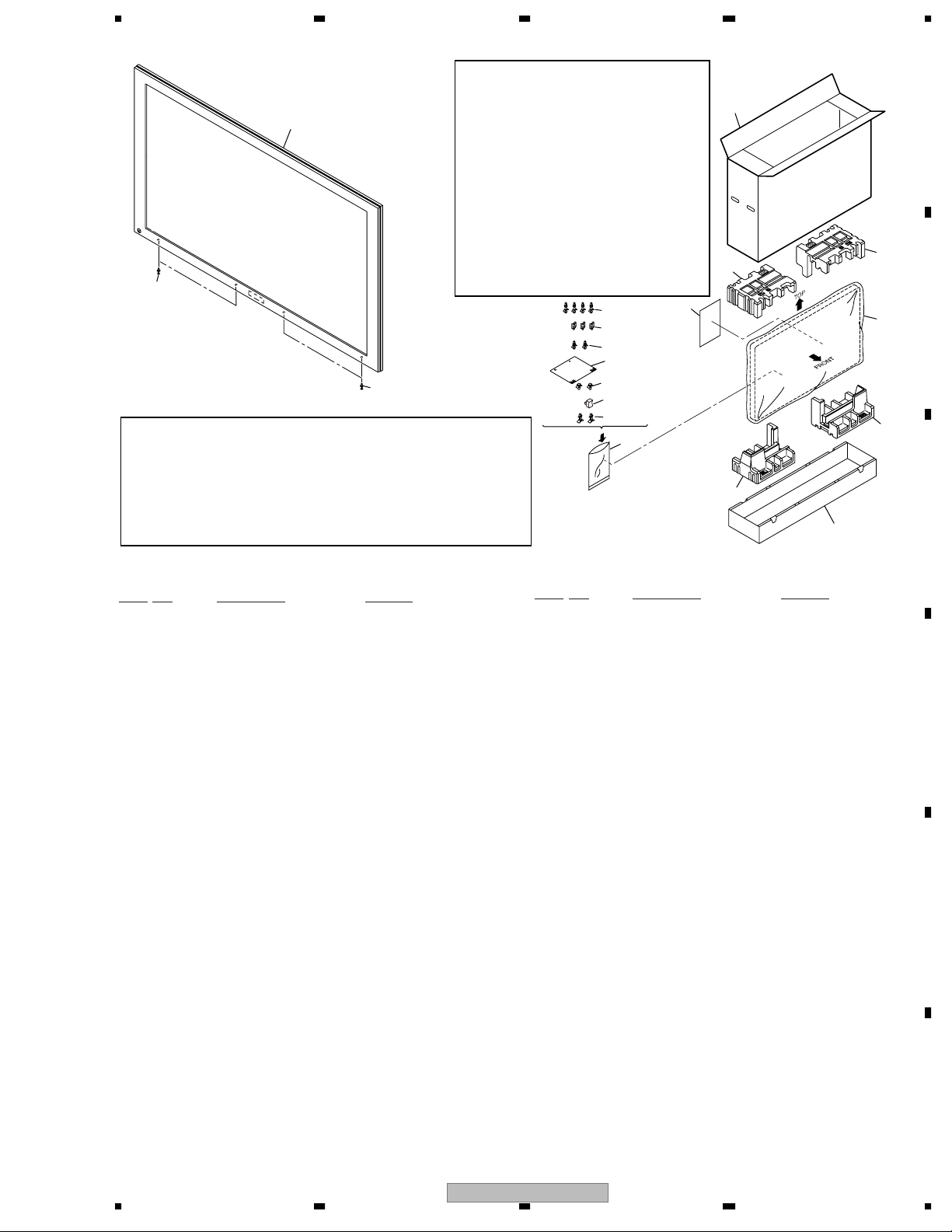
EXPLODED VIEWS AND PARTS LIST
The mark found on some component parts indicates the importance of the safety factor of the part.
Therefore, when replacing, be sure to use parts of identical designation.
Screws adjacent to mark on product are used for disassembly.
(In the case of no amount instructions, apply as you think it appropriate.)
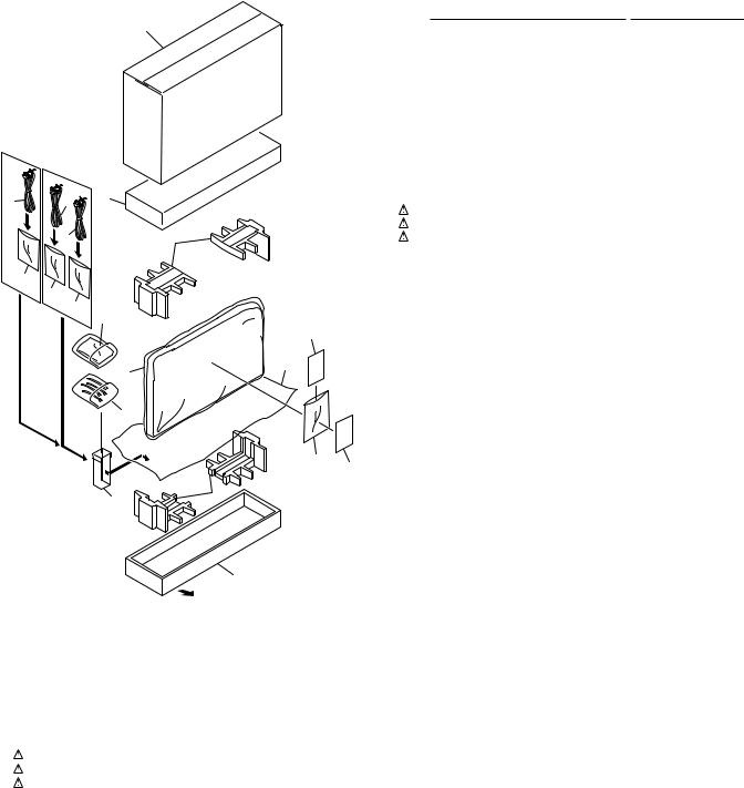
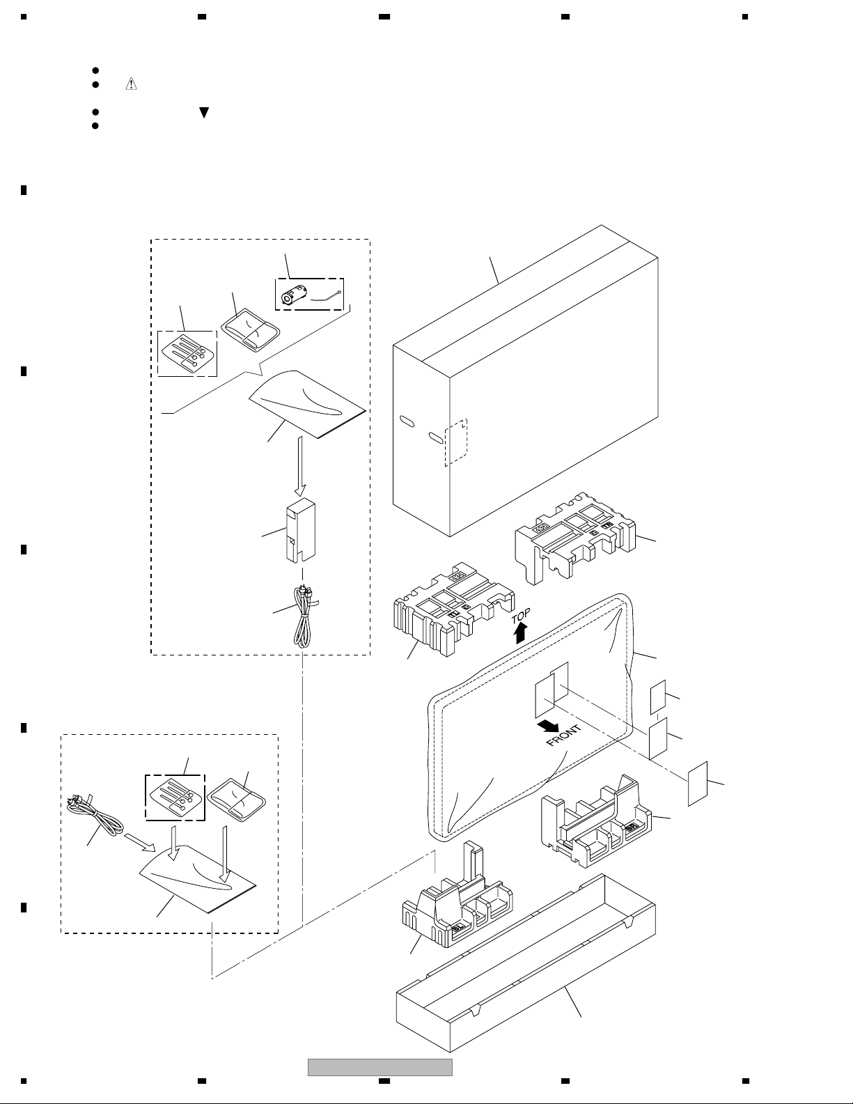
(1) PACKING SECTION PARTS LIST
No. Description Part No.
1Power Cord See Contrast table (2)
2 Binder Assy AEC1908
3 Cleaning Cloth AED1285
4Polyethylene Bag S See Contrast table (2)
NSP 5 Catalogue Bag See Contrast table (2)
NSP 6 Warranty card See Contrast table (2)
7Ferrite Core See Contrast table (2)
8Pad (43T-L) See Contrast table (2)
9Pad (43T-R) See Contrast table (2)
10 Pad (43B-L) See Contrast table (2)
11 Pad (43B-R) See Contrast table (2)
12 Power Cord Case See Contrast table (2)
13 Under Carton See Contrast table (2)
14 Upper Carton See Contrast table (2)
15 Mirror Mat See Contrast table (2)
16 Caution Card See Contrast table (2)
Mark No. Symbol and Description PDP-436PE/WYVI PDP-436PU/KUCXC
1Power Cord ADG1214 ADG1215
4Polyethylene Bag S AHG1338 AHG1348
NSP 5 Catalogue Bag AHG1340 AHG1347
NSP 6 Warranty Card ARY1114 ARY1145
7Ferrite Core ATX1039 Not used
8Pad (43T-L) AHA2431 AHA2463
9Pad (43T-R) AHA2432 AHA2464
10 Pad (43B-L) AHA2433 AHA2465
11 Pad (43B-R) AHA2434 AHA2466
12 Power Cord Case AHC1073 Not used
13 Under Carton (436) AHD3346 Not used
13 Under Carton (436PU) Not used AHD3380
14 Upper Carton (436PE) AHD3368 Not used
14 Upper Carton (436PU) Not used AHD3384
15 Mirror Mat AHG1284 AHG1352
16 Caution Card ARM1232 ARM1239
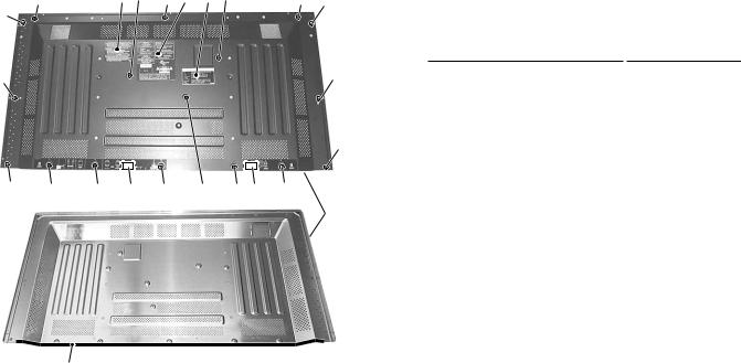
2 REAR SECTION
“2.3 FRONT SECTION”.
(1) REAR SECTION PARTS LIST
1AC Inlet AKP1274
2 Control Plate AND1185
3 Rear Case (436) ANE1640
4 Inner Grip Assy AMR3434
5AC Cushion AEC2035
NSP 6 Model Label See Contrast table (2)
7 Caution Label See Contrast table (2)
8AC Label PE See Contrast table (2)
9• • • • •
10 • • • • •
11 Screw (3 x 40P) ABA1332
12 Hexagon Head Screw BBA1051
13 Screw PMZ26P060FTB
14 Screw BPZ30P080FTB
15 Screw AMZ30P060FTB
16 Screw TBZ40P080FTB
NSP 6 Model Label (436PE) AAL2670 Not used
NSP 6 Model Label (436PU) Not used AAL2680
7 Caution Label AAX3117 AAX3075
8AC Label PE AAX3194 Not used
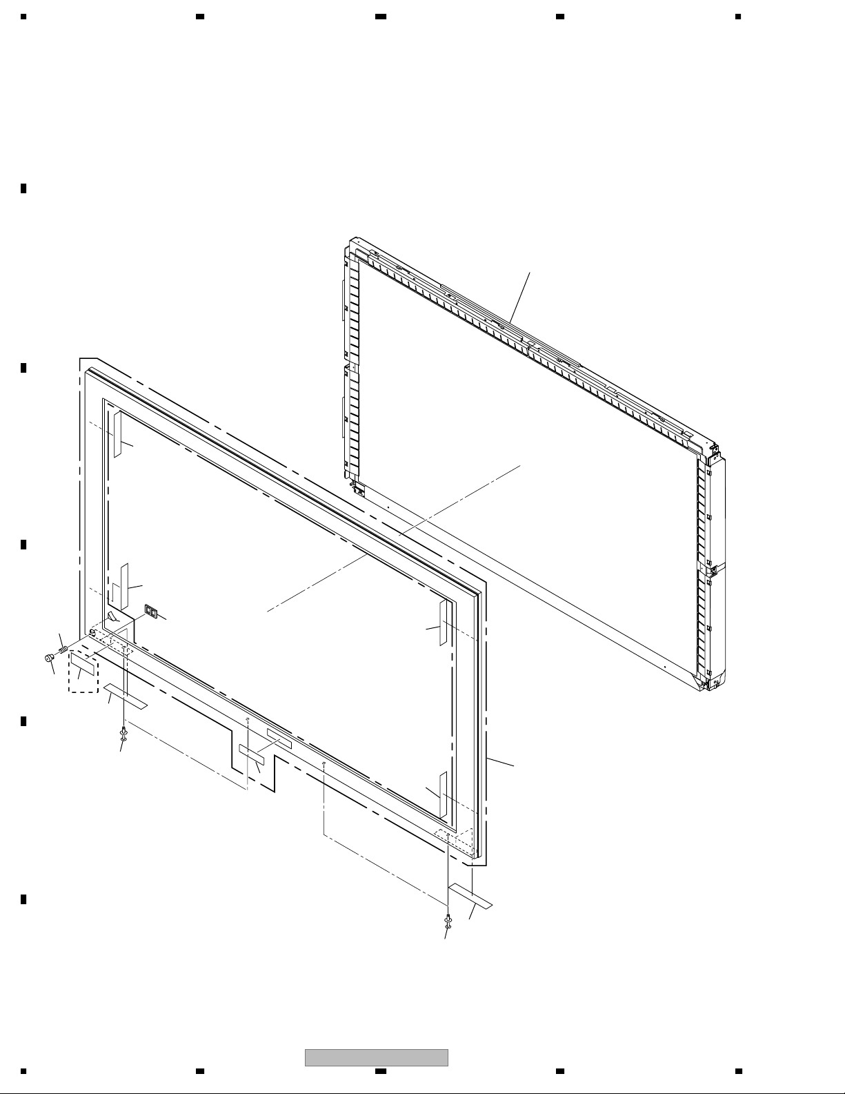
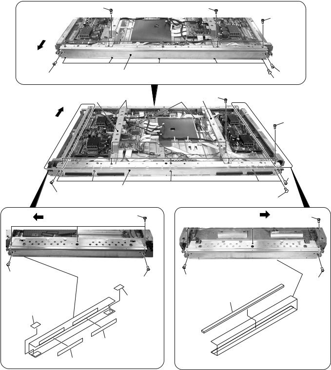
3 FRONT SECTION
“2.4 CHASSIS SECTION (1/2)”,
(1) FRONT SECTION PARTS LIST
1Front Case Assy (436PE) AMB2855
2 Corner Cushion AEB1416
3 Pioneer Name Plate AAM1096
4Power Button AAD4133
5 Coil Spring ABH1120
6 Blind Cushion AEB1415
7 Insulation Sheet A AED1283
8 Insulation Sheet B AED1284
9Power Display Label (436) See Contrast table (2)
10 Screw Rivet AEC1877
9Power Display Label (436) AAX3205 Not used
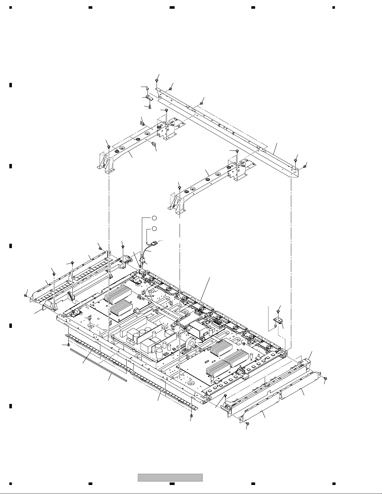
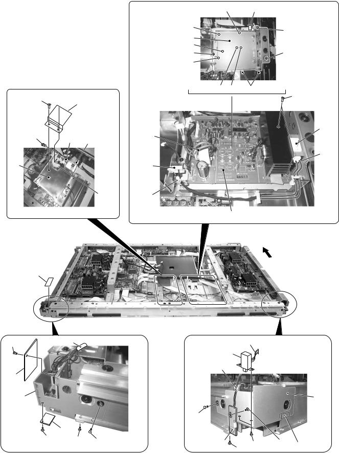
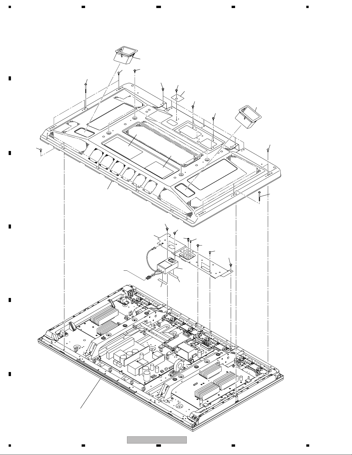
4 CHASSIS SECTION (1/2)
From AC Inlet
From POWER SUPPLY
“2.5 CHASSIS SECTION (2/2)”.

CHASSIS SECTION (1/2) PARTS LIST
1 HD LED Assy AWW1029
2 HD IR Assy AWW1030
3Power Switch (S1) ASG1092
4 Housing Wire (43)(J103) ADX3126
5Front Chassis VL (43) AMA1016
6Front Chassis VR (43) AMA1017
7 Sub Frame L Assy (436) ANA1864
8 Sub Frame R Assy (436) ANA1865
9Front Chassis H Assy (43) ANA1884
10 Panel Holder H (43) ANG2772
11 Panel Holder V1 (43) ANG2773
12 Panel Holder V2 (43) ANG2774
13 Cushion AEB1424
14 Wire Saddle AEC1745
15 • • • • •
16 Nyron Rivet AEC1671
17 Screw ABZ30P080FTC
18 Screw AMZ30P060FTB
19 Screw APZ30P080FTB
20 Screw BBZ30P060FTC
21 Screw BPZ30P080FTB
22 Screw TBZ40P080FTB
23 Screw VBB30P080FNI
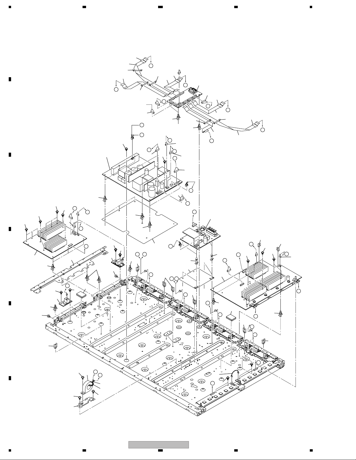
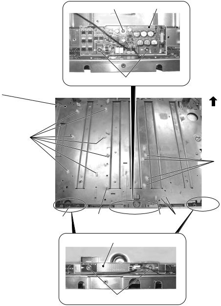
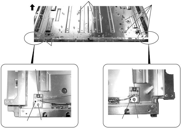
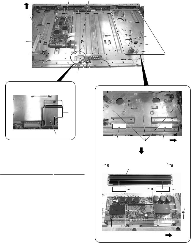
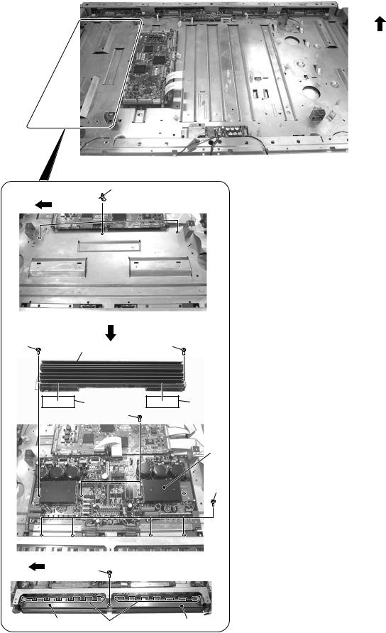
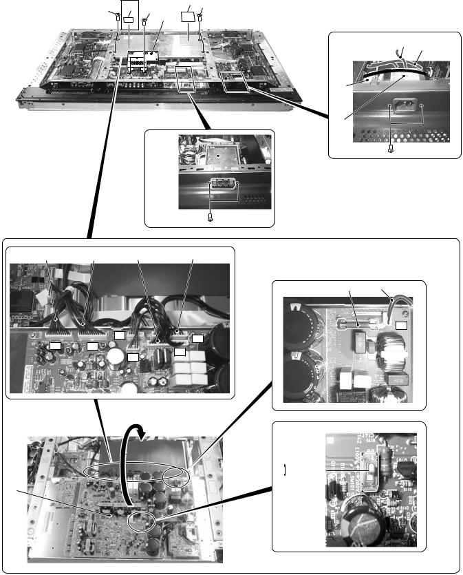
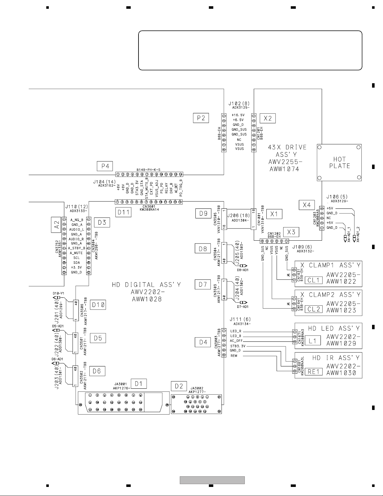
5 CHASSIS SECTION (2/2)
To HD LED CN1671
HD IR CN1681

CHASSIS SECTION (2/2) PARTS LIST
1 43 X DRIVE Assy AWW1074
2 SUS CLAMP 1 Assy AWW1022
3 SUS CLAMP 2 Assy AWW1023
4 43 Y DRIVE Assy AWV2256
5 HD DIGITAL Assy AWW1028
6 HD AUDIO Assy AWV2203
7POWER SUPPLY Unit AXY1112
8 Ring Core with Case ATX1042
9Ferrite Core ATX1048
10 Flexible Cable (J201) ADD1299
11 Flexible Cable (J202) ADD1300
12 Flexible Cable (J203) ADD1301
13 Flexible Cable (J204) ADD1302
14 Flexible Cable (J205) ADD1303
15 Flexible Cable (J206) ADD1304
16 4P Housing Wire (J108) ADX3131
17 6P Housing Wire (J109) ADX3132
18 12P Housing Wire (J110) ADX3133
19 6P Housing Wire (J111) ADX3134
20 3P Housing Wire (J113) ADX3136
21 14P Housing Wire (J104) ADX3162
22 3P Housing Wire (J105) ADX3128
23 9P Housing Wire (J101) ADX3124
24 8P Housing Wire (J102) ADX3125
25 5P Housing Wire (J106) ADX3129
26 6P Housing Wire (J107) ADX3130
27 Conductive Plate XA ANG2776
28 FC Stay ANG2815
29 Binder AEC-093
NSP 30 PCB Spacer AEC1188
31 Flat Clamp AEC1879
32 PCB Spacer AEC1941
33 Drive Silicone Sheet AEH1095
34 Power Supply Insulation Sheet AMR3447
35 Audio Insulation Sheet AMR3469
36 Wire Saddle AEC1745
37 • • • • •
38 Mini Clamp AEC1971
39 Screw ABA1324
40 Screw PMB30P060FTC
41 Screw VBB30P080FNI
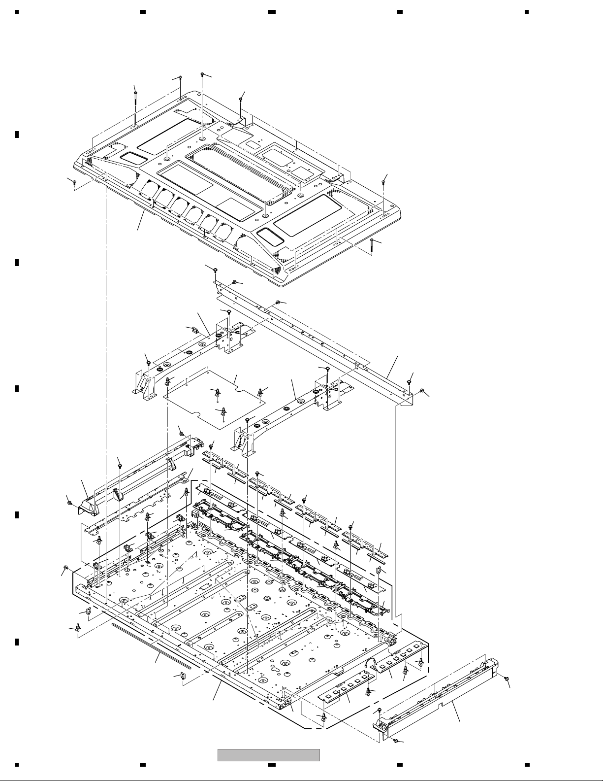
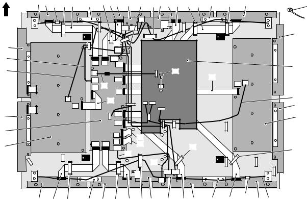
6 PDP SERVICE ASSY 436P (AWU1135)
PDP SERVICE ASSY 436P (AWU1135) PARTS LIST
• Front Section • Packing Section
The Power Switch (S1), HD LED Assy, and HD IR Assy are not included
in the PDP Service Assy 436P. Before replacement with the PDP Service
temporarily detached to attach the above-mentioned parts (parts from
the original unit or newly purchased):
• Front Chassis H Assy (43) (ANA1884)
• Front Chassis VL (43) (AMA1016)
• Front Chassis VR (43) (AMA1017)
Some parts of the PDP Service Assy 436P
are provided as supplied accessories:
1 PCB spacer (AEC1188) 4
2 Wire saddle (AEC1745) 3 (out of 20)
3 PCB spacer (AEC1941) 2 (out of 22)
4 Audio sheet (AMR3469)
5 PCB Support (AEC1938) 2
(not used in this product)
6 Ferrite Core Holder (AEC1818) 1
7 Circuit Board Spacer (AEC1872) 2
For details on reattachment, refer to the
“Instructions on Panel Replacement (6G)
(ARM1287),” included in the service-part kit.
Note when replacing with the PDP Service Assy 436P
NSP 1 Panel Chassis (436) Assy AWU1145
NSP 2 43 ADDRESS Assy AWV2204
NSP 3 43 SCAN A Assy AWW1018
NSP 4 43 SCAN B Assy AWW1019
5 PCB Spacer AEC1944
6 Conductive Plate Holder AMR3446
7 Address Holder Assy (436) AMR3455
8Tube Cover AMR3445
NSP 9 Chassis Assy (436) ANA1833
10 Front Chassis VL (43) AMA1016
11 Front Chassis VR (43) AMA1017
12 Sub Frame L Assy (436) ANA1864
13 Sub Frame R Assy (436) ANA1865
14 Front Chassis H Assy (43) ANA1884
15 Address Heatsink (436) ANH1641
16 Conductive Plate XA ANG2776
17 Cushion AEB1424
18 Power Supply Insulation Sheet AMR3447
19 Wire Saddle AEC1745
20 Screw Rivet AEC1877
21 PCB Spacer AEC1941
22 Address Silicone A AEH1093
23 Front Case Assy 436 service AMB2895
(for transportation: please do not use for repair)
24 Rear Case (436) ANE1640
25 • • • • •
26 • • • • •
27 • • • • •
28 • • • • •
29 • • • • •
30 Protect Sheet AHG1331
31 Screw (3x40P) ABA1332
32 Screw ABZ30P080FTC
33 Screw AMZ30P060FTB
34 Screw APZ30P080FTB
35 Screw BBB30P120FNI
36 Screw PMB30P060FTC
37 Screw TBZ40P080FTB
38 Screw VBB30P080FNI
39 Pad (43T-L) AHA2431
40 Pad (43T-R) AHA2432
41 Pad (43B-L) AHA2433
42 Pad (43B-R) AHA2434
43 Under Carton AHD3346
NSP 44 Upper Carton AHD3436
NSP 45 Exchange Panel Sheet ARM1287
46 Vinyl Bag S AHG1338

BLOCK DIAGRAM AND SCHEMATIC DIAGRAM
LIST” or “PCB PARTS LIST”.
The mark found on some component parts indicates the importance of the safety
factor of the part. Therefore, when replacing, be sure to use parts of identical
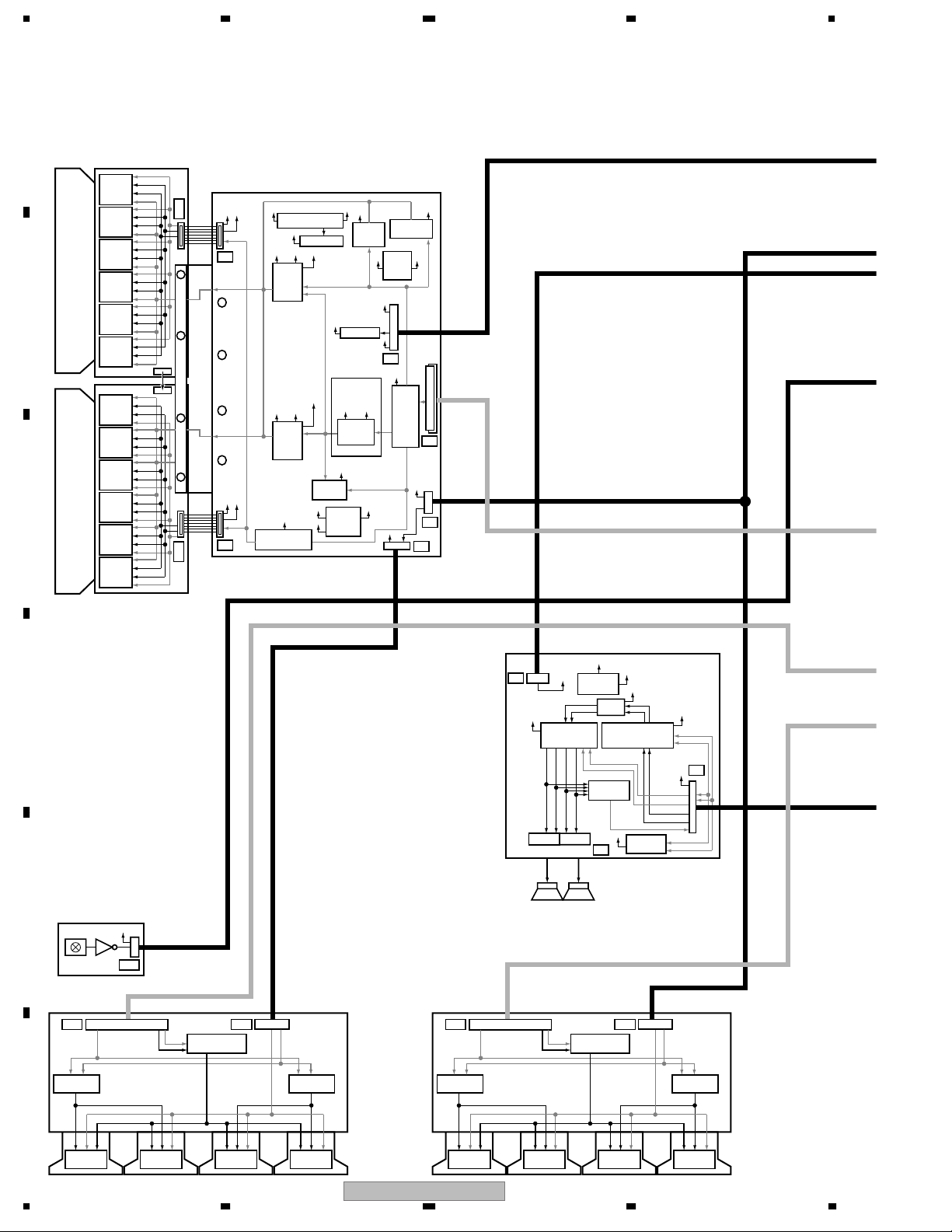
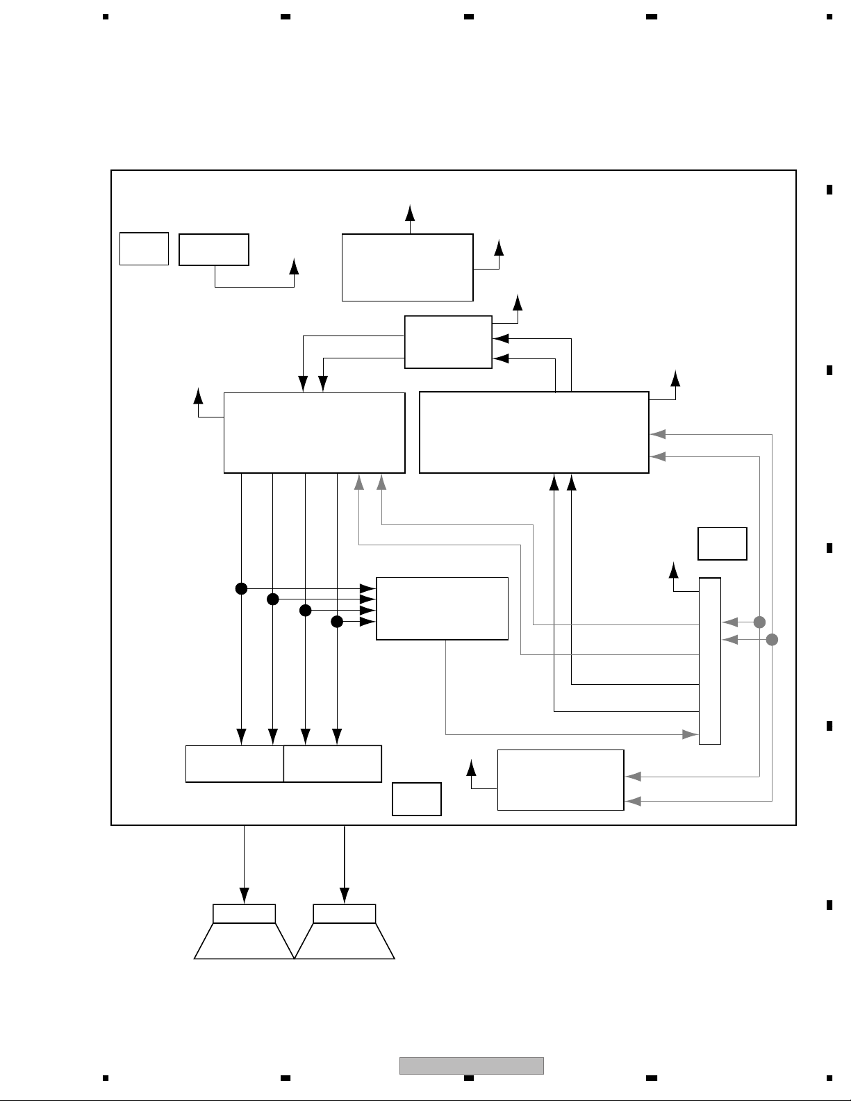
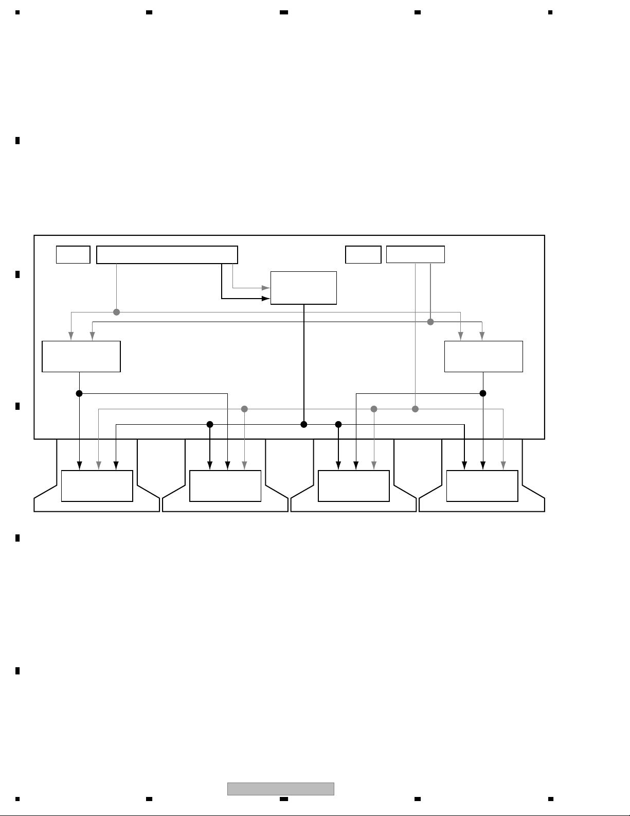
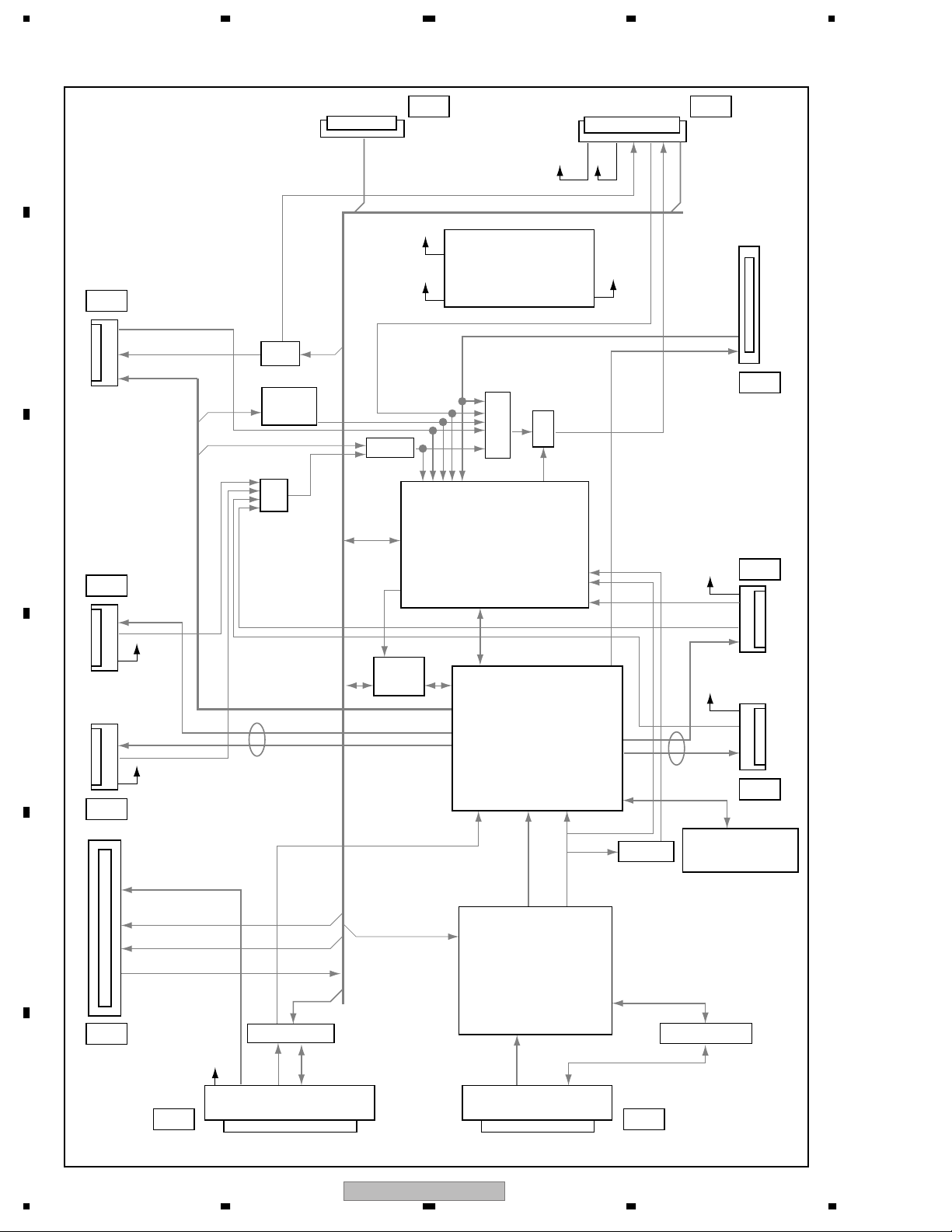
2 OVERALL BLOCK DIAGRAM
AN/P BN/P
CN/P DN/P CLKN/P
IR Receive unit
Power Amp IC
WOW + Volume IC
VH DC/DC Conv.
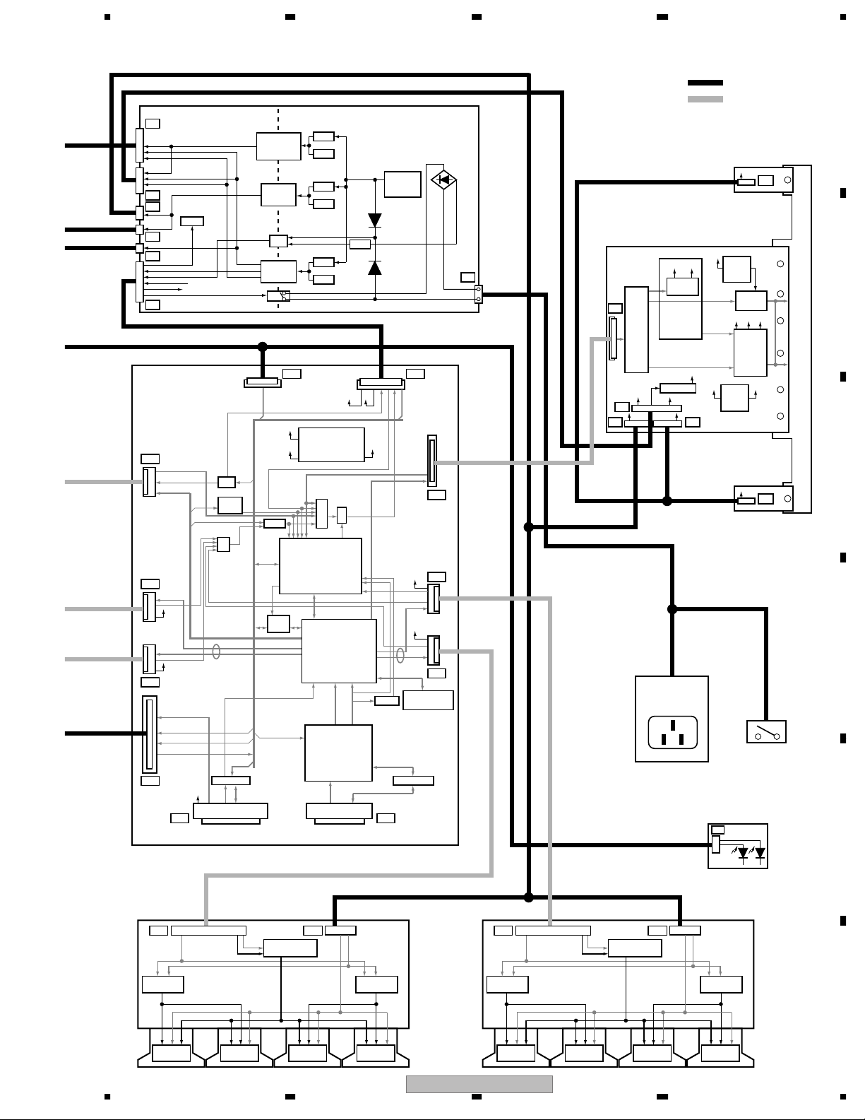
DVI CONNECTORMDR CONNECTOR
: Wire haerness
DCLK, DERA, GA, BA
3 43 ADDRESS ASSY
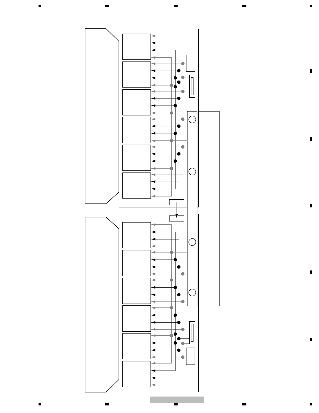
4 43 SCAN A and B ASSYS
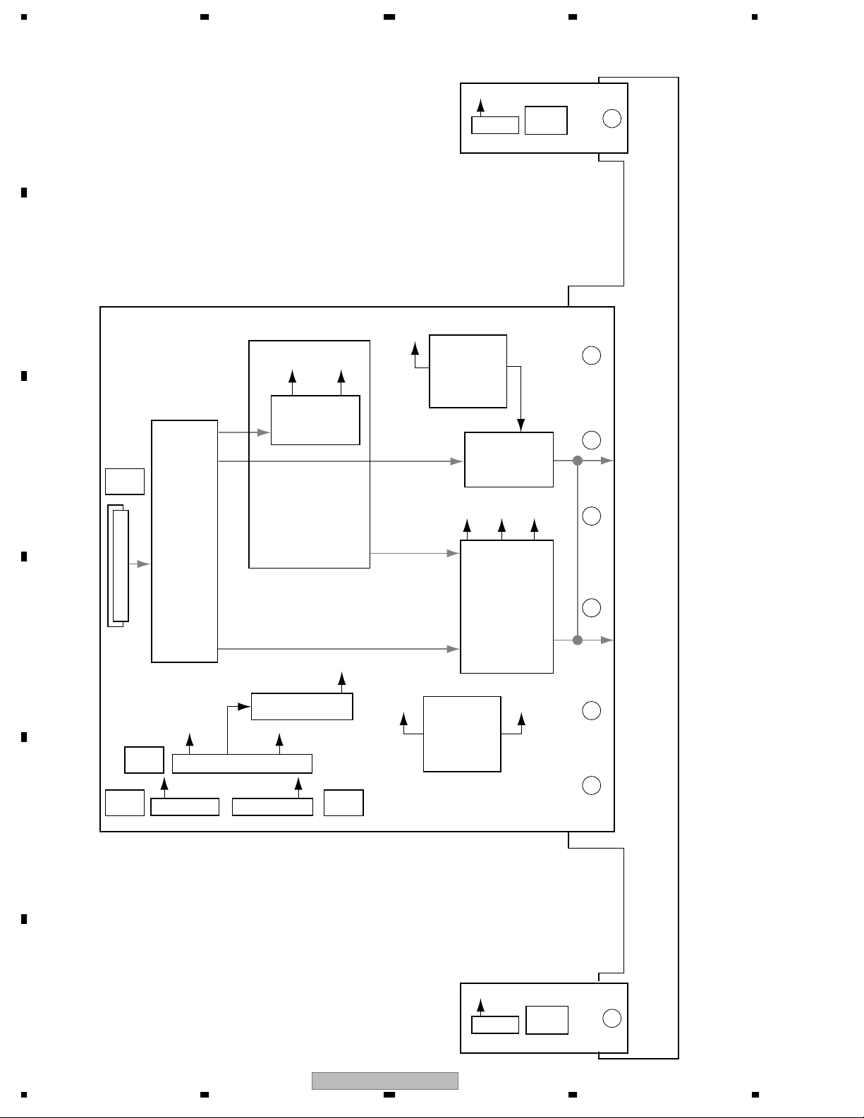
5 43 X DRIVE, SUS CLAMP 1 and SUS CLAMP 2 ASSYS
6 43 Y DRIVE ASSY
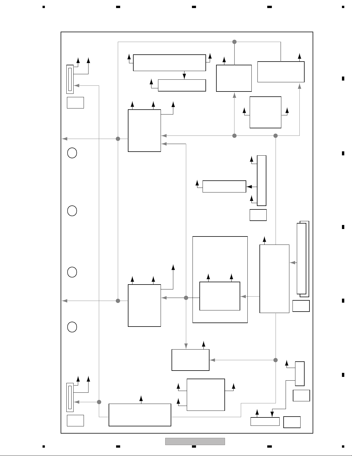
7 HD DIGITAL ASSY